
The world of rowing is constantly flowing and evolving with HUDSON™ and its team at the heart of the action. Stay in current with articles and events straight from the SHARK's mouth, or explore more about HUDSON and our history in the industry.
California Rowing Club selects HUDSON as official performance partner
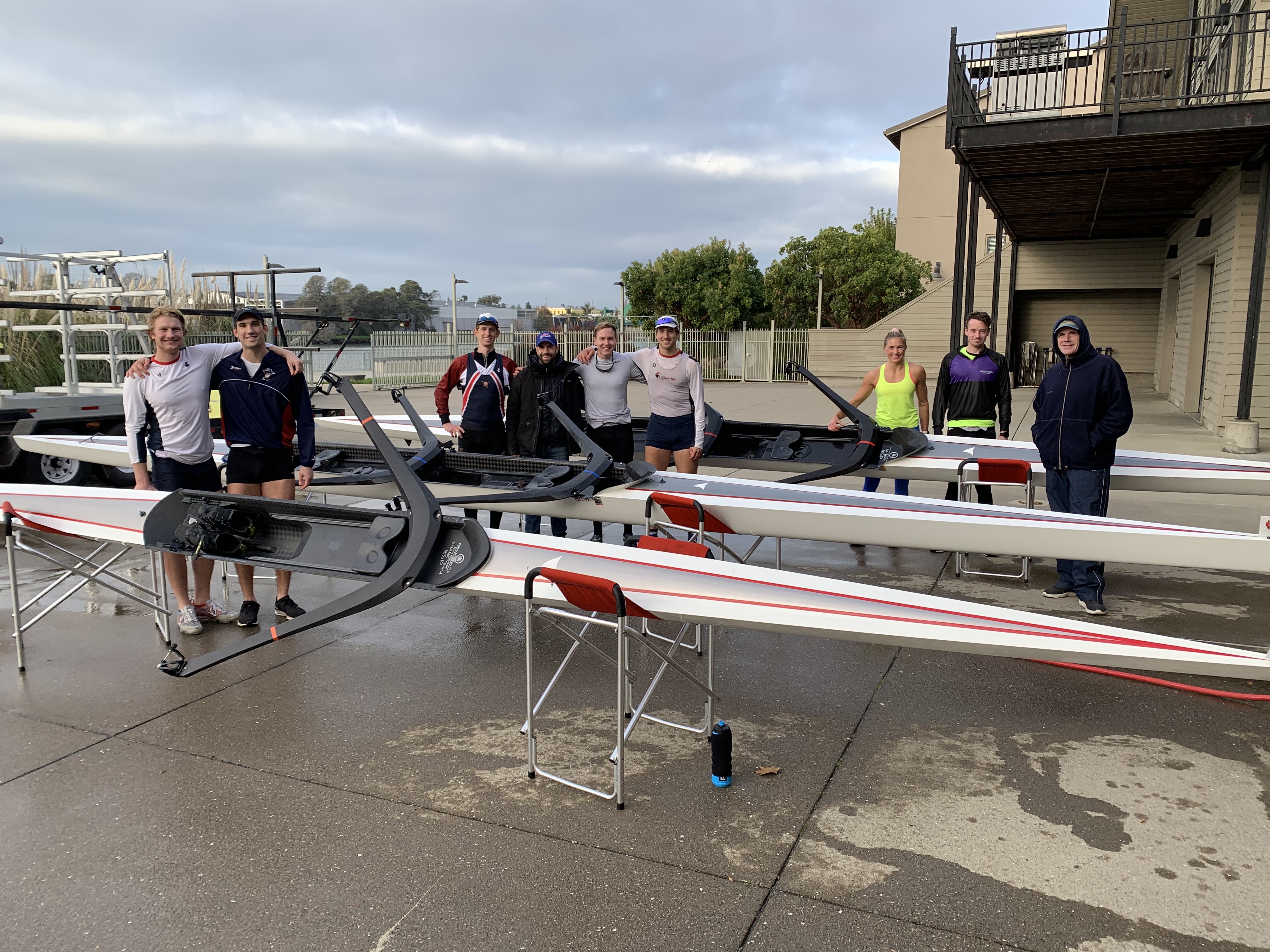
DECEMBER 20TH, 2021 – California Rowing Club (CRC) has selected HUDSON Boat Works as their official performance partner, effective December 1st, 2021.
Working in collaboration with CRC coaches Mike Teti and Skip Kielt, HUDSON will provide training equipment to the center in Oakland, CA as well as racing equipment for domestic and international competition.
“Our relationship with HUDSON was built on trust… but ultimately our decision to row a USP was based on performance” said CRC Coach Skip Kielt. “CRC athletes will have access to the best equipment to race in for both domestic and international competition with HUDSON.”
According to a press-release published by CRC in October, “California Rowing Club is very excited to embrace the new athlete-focused model for USRowing. Qualified athletes who choose to train at the CRC will not only find exceptional coaching talent and the ability to train year-round, but also world class training equipment, physical therapy, and boathouse facilities.”
SHARK team athlete Ben Davison, is one of the athletes currently training at CRC. “I can’t thank HUDSON enough for their support of me and my teammates at CRC,” said Davison. “Their world-class equipment and service allow me to pursue my goal of competing at the highest level.” Most recently, Davison won the Men’s Champ 1x in a HUDSON USP at the 2021 Head of the Charles Regatta®.
Athletes that are invited to train at the California Rowing Club located in the Ebright Boathouse at the T.Gary Rogers Rowing Center in Oakland, CA will be under the direction of long-time Olympic and National Team Coach Mike Teti, along with Coach Skip Kielt.
“As alumni of the US National Team, Matt [Muffelman] and I are excited to provide the championship levels of support and service to the next generation of U.S. athletes at the California Rowing Club,” former Olympic Rower and HUDSON Sales Representative Dan Walsh said. “Mike's coaching has helped US crews succeed at the highest levels of competition, nationally and internationally. The last time the United States won a gold medal in the Men’s 8+ at the Olympic Games was in 2004 while rowing a HUDSON, coached by Teti.”
---
For more information on the California Rowing Center, please visit:
https://californiarowingclub.squarespace.com/.
For more information on HUDSON Boat works and the USP models, please visit:
A Most Beautiful Thing Inclusion Fund gets real in Chicago
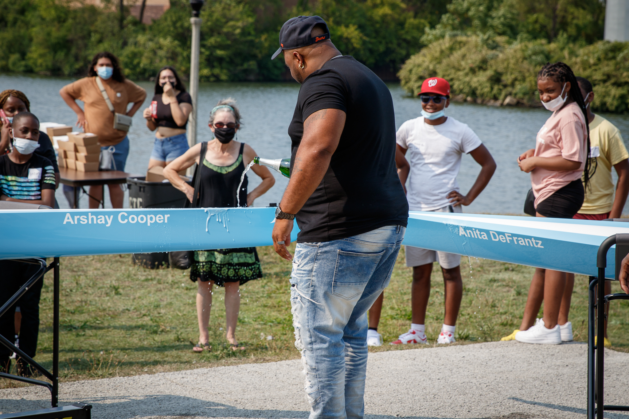
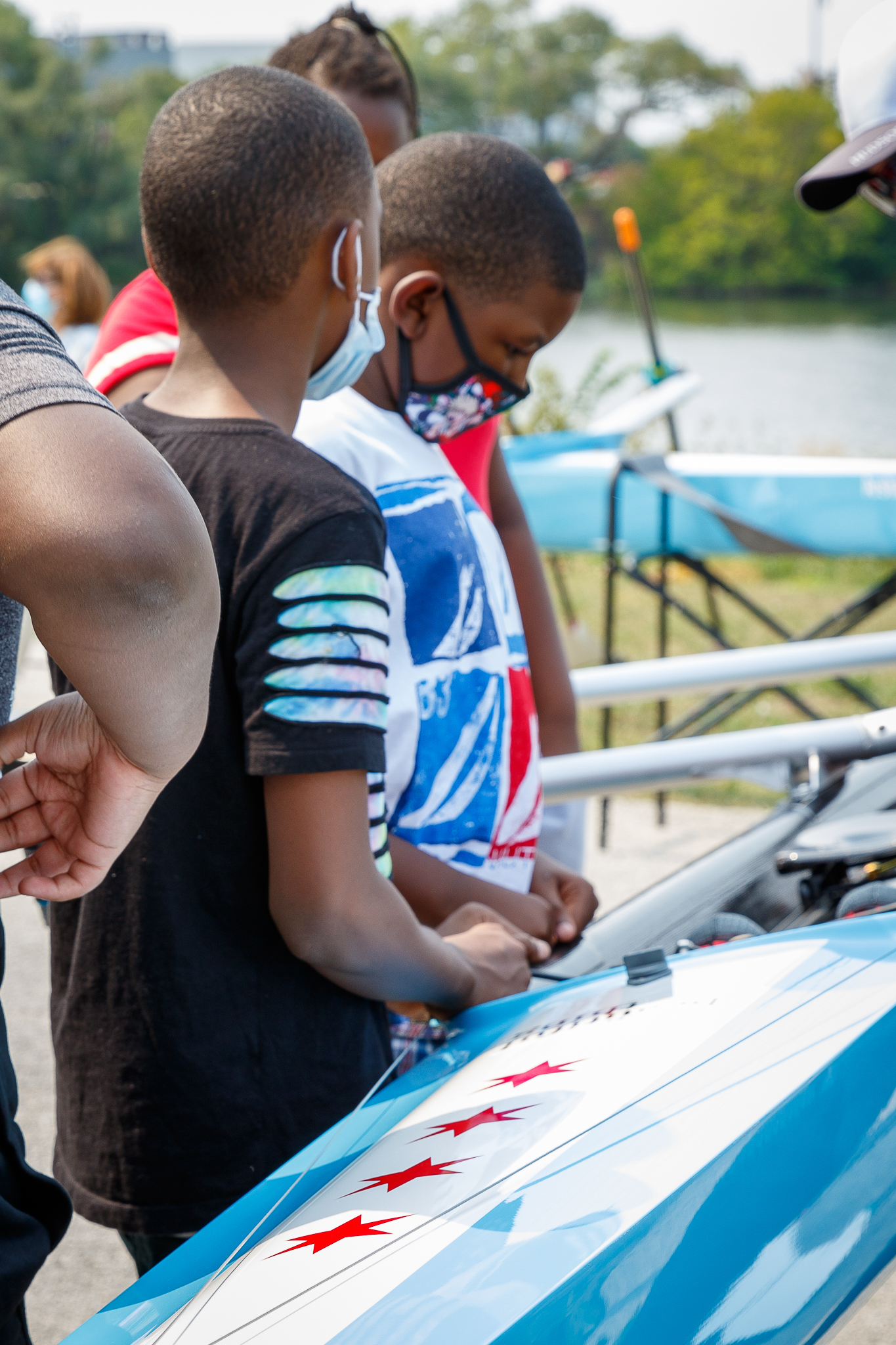 SEPTEMBER 2021 | Arshay Cooper and the greater rowing community of Chicago celebrated the new partnership between the A Most Beautiful Thing Inclusion Fund (AMBTIF) and Chicago Training Center (CTC), the first of five selected core programs to receive support from AMBTIF and industry partners, HUDSON and Concept2.
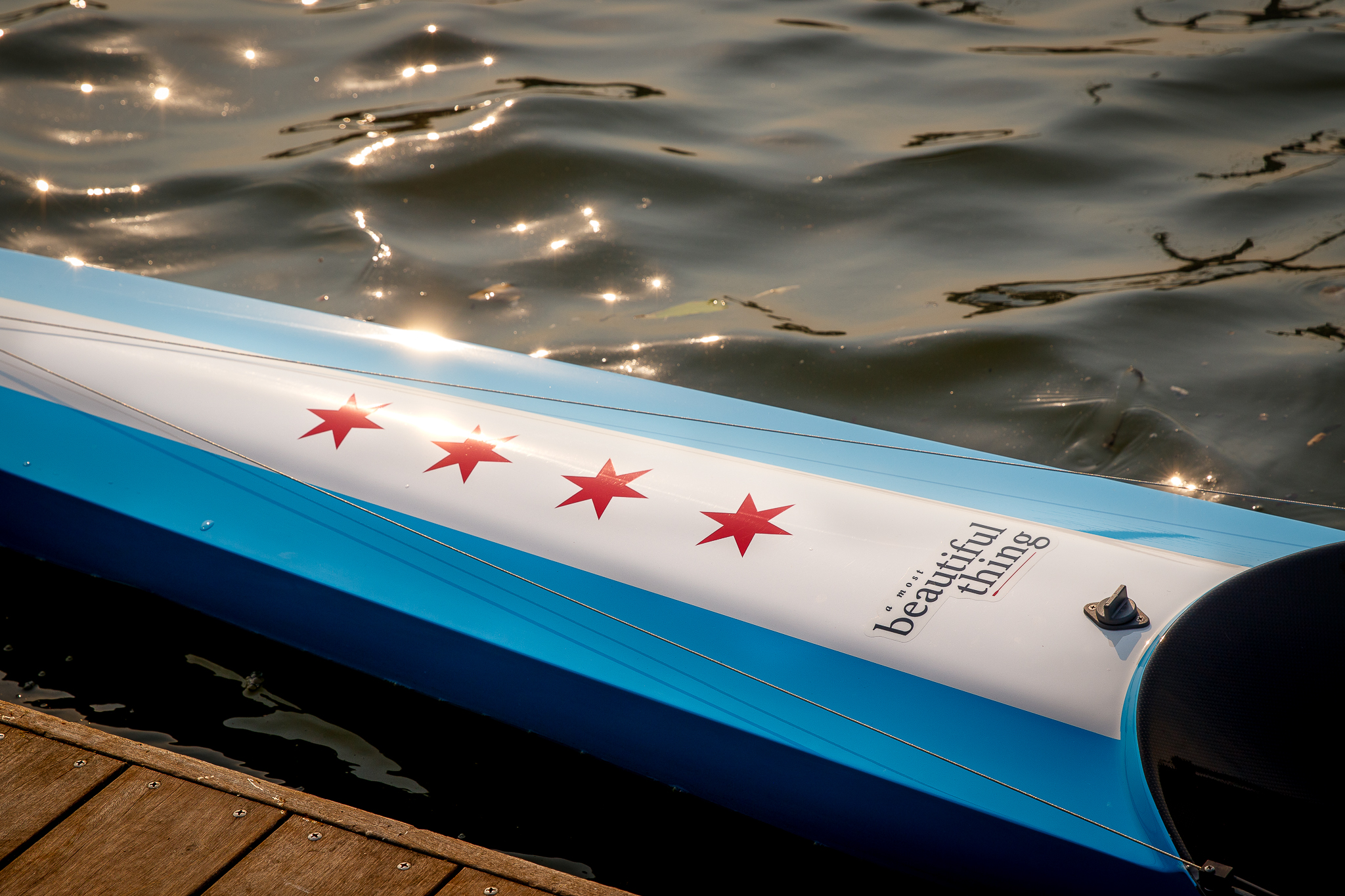
The event featured a learn-to-row experience for interested students, the unveiling and christening of new Chicago-inspired HUDSON SHARK boats, guest speakers from The Obama Foundation and the WNBA Chicago Sky, live music, and special appearances by members of the Manley High School Crew and Chicago Police Department featured in the award winning A Most Beautiful Thing documentary film directed by Mary Mazzio.
“AMBTIF is premised on the belief that rowing, when paired with strong academic support, yields very powerful returns. Rowing teaches work ethic, teamwork, and resilience, while also fostering leadership, tenacity, and ambition in its participants” author and documentary film star Arshay Cooper said.
Programs selected by AMBTIF will receive dedicated grants to support coaches of color, transportation, swimming lessons, & academic tutoring, and racing in local and regional regattas competing in world-class HUDSON SHARK Pair/Doubles and Concept2 Oars and Ergometers. Additionally, the AMBTIF will provide ongoing DEI training to all its partners and feature Arshay, along with role model guest athletes, to work with each partner city recipient program on athlete recruitment.
The five core programs receiving grants and equipment in Year 1:
- Chicago Training Center (Chicago, IL)
- St Benedict's Preparatory School - Rowing Team (Newark, NJ)
- Baltimore Community Rowing (Baltimore, MD)
- San Miguel Academy - Rowing Team (Newburgh, NY)
- Delta Sculling Center (Stockton, CA)
“We are proud to be partners with an initiative that will positively impact the sport of rowing. We believe in Arshay’s mission which will realize more diverse athletes being represented in our sport,” said Dan Walsh, the industry liaison for HUDSON and Concept2. “HUDSON is proud to present two world-class, Chicago-inspired, Pair/Doubles to The Chicago Training Center and the other four core recipient programs in this inaugural year of the AMBTIF.”
For more information on upcoming AMBTIF events, visit arshaycooper.com.
HUDSON Signs Four-Year Partnership with USRowing Under 19 National Team
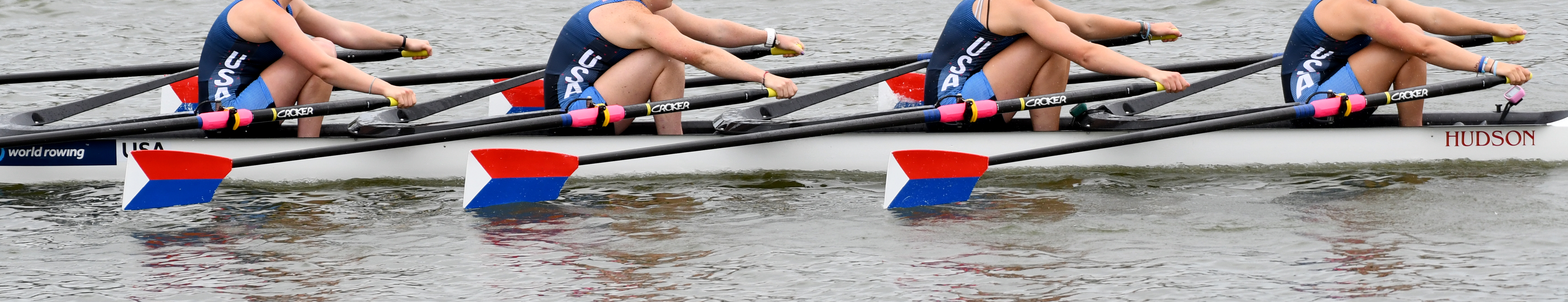
DECEMBER 2021 | HUDSON has signed a four-year sponsorship agreement with USRowing to support its Under 19 National Team through 2024, effective immediately.
In this partnership, HUDSON will supply racing shells for selection and training domestically with matched shells provided internationally for racing. Through their global network, HUDSON is able to provide world-class service both in the US and abroad.
“I know I speak on behalf of everyone at HUDSON in saying how excited we are to support the USA’s U19 national team and all of their aspiring high-performance athletes,” Director of HUDSON USA Matt Muffelman said.
The agreement covers all of the Under-19 National Team camp boats including the women’s eight, men’s eight, women’s four with coxswain, men’s four with coxswain, women’s quadruple sculls, men’s quadruple sculls, women’s four, and men’s four. Overseen by USRowing U19 Director and Head Coach Casey Galvanek, Caitlin McClain and Eric Gehrke will serve as the head coaches of the U19 women and U19 men, respectively, through the 2021 World Rowing Junior Championships in Plovdiv, Bulgaria, later this summer.
According to Chris Chase, USRowing Director of Youth Rowing, the goal for the junior team is to expand and provide resources to aspiring elite athletes through equipment, coaching and overall accessibility to the sport of rowing.
“If we have a partner that we can rely on for continued support via equipment and service, it allows us to focus our energy and resources in creating a better overall experience for the aspiring athlete. HUDSON was the optimal choice.”
Chase said that while there are many aspects to the partnership that will positively influence the growth of future junior programming and development, HUDSON’s recent expansion in the Sarasota area (particularly NBP) played a significant role in the decision.
“It’s obviously a project and a pursuit that’s near and dear to my heart,” Muffelman said. Muffelman, a HUDSON employee and Sarasota resident, spent a decade training and competing on the USRowing national team.
“Generation SHARK is upon us. I’m thrilled to see HUDSON moving forward at full speed in the USA,” said Muffelman.
For more information on junior programming, please visit: www.usrowing.org.
HUDSON partners with RIVERSPORT Foundation
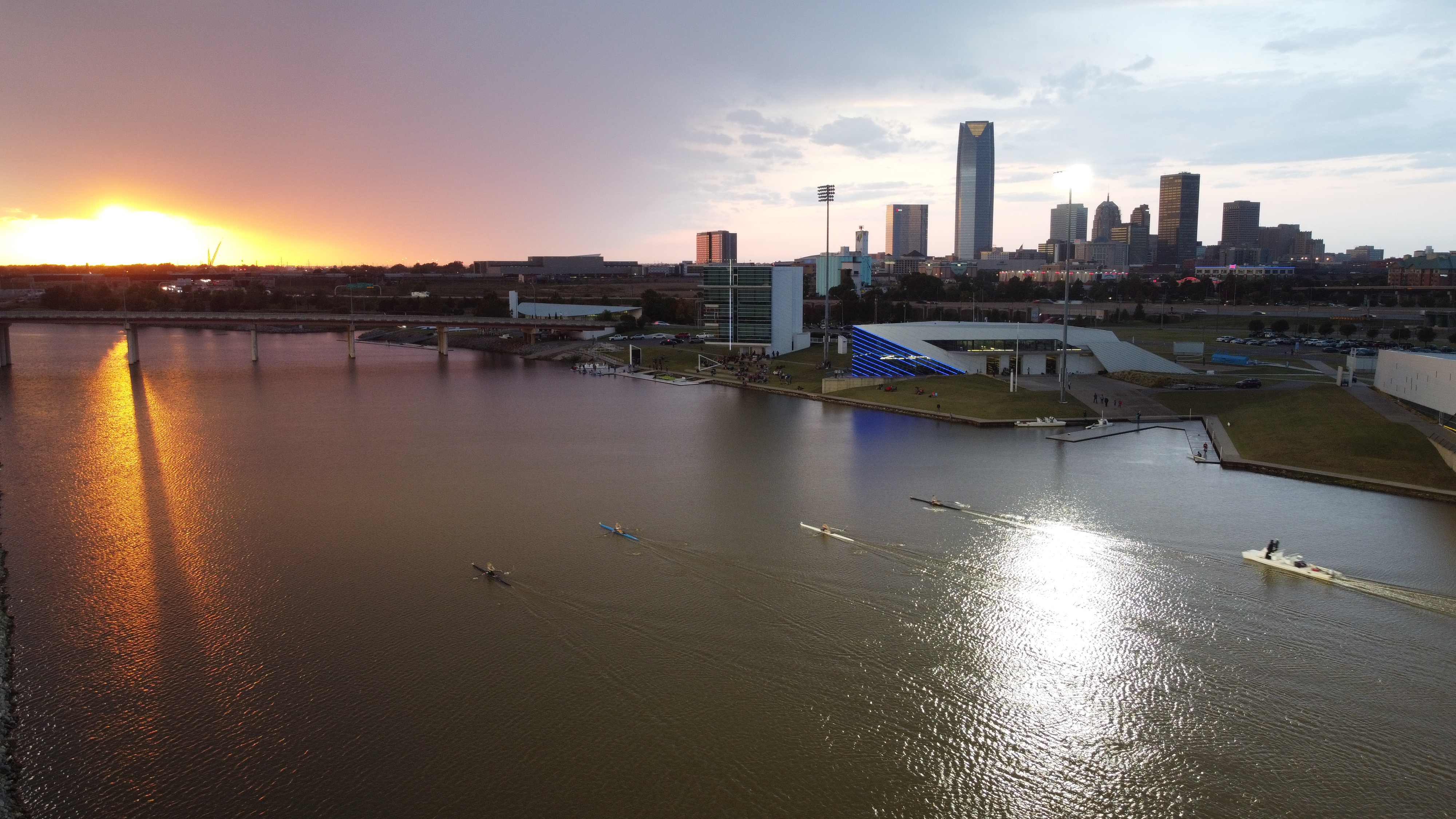
JANUARY 2021 | Industry-leading boat manufacturer HUDSON is pleased to announce a partnership with the USRowing National High-Performance Training Center at OKC and the RIVERSPORT Foundation, to support and enhance the state-of-the-art training facility in Oklahoma City, Oklahoma.
“As an Olympian, I know it takes a community to be able to reach the next level in your athletic career,” 2008 Olympic Medalist and HUDSON Central Region Representative Liam Parsons commented. “You need reliable resources, coaching, consistency and support among many other things. To not have to worry about the performance or reliability of your equipment is huge. I’m glad that we can bring this type of support to the athletes currently training in OKC.”
As the current Head Coach and High-Performance Program Director for the USRowing National High-Performance Center, Reilly Dampeer has been supporting elite athletes since 2016. Athletes that have been part of the group that trains in OKC have seen success at the Senior, U23 and U19 World Championships, Pan American Games, and World Cups among notable events.
“OKC has selected HUDSON as the primary boat manufacturer for all RIVERSPORT programming,” Dampeer stated. “The quality and performance of equipment, as well as the superior service from their staff, made this decision easy. We have a strategic plan through LA28 and HUDSON aligns with everything we are hoping to accomplish in the upcoming years.”
In addition to supporting the athletes and coaches at USRowing National High-Performance Center at OKC, HUDSON will play a significant role in general programming that is offered through the RIVERSPORT Foundation Boathouse District.
“Building a culture for rowing in OKC from the ground up was anchored with the belief that we needed to introduce the sport as a mainstream activity to re-acquaint our city to the river that our city was built upon literally overnight,” said RIVERSPORT Foundation Executive Director Mike Knopp.
“The spirit of innovation is shared between HUDSON and RIVERSPORT and we greatly look forward to this timely partnership given our aggressive and exciting vision for growth of our programming and reach over the next few years.”
HUDSON Atlantic Sales Manager Matt Muffelman is particularly pleased with the continued excitement surrounding rowing in the OKC community. “It’s amazing to look at the growth of rowing in Oklahoma over the past decade and how instrumental Mike and the OKC community have been. The enthusiasm that drives all their programming is contagious. I’m thrilled that HUDSON has this opportunity to further aide in the growth of the sport in the region.”
For more information about the USRowing National High-Performance Training Center at OKC or the RIVERSPORT Foundation, please visit riversportokc.org.